We BuildConcrete Systems
For Clean and Safe Water
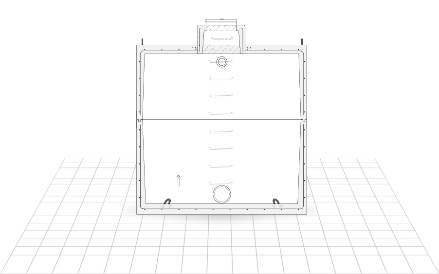
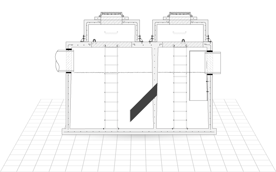
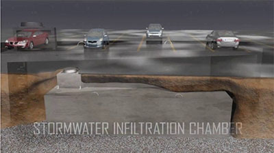
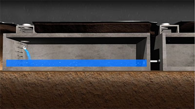
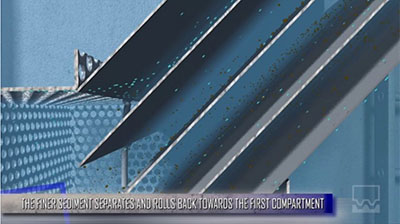
Our durable precast units provide reliable water management for municipalities, construction companies and home owners for 65 years.

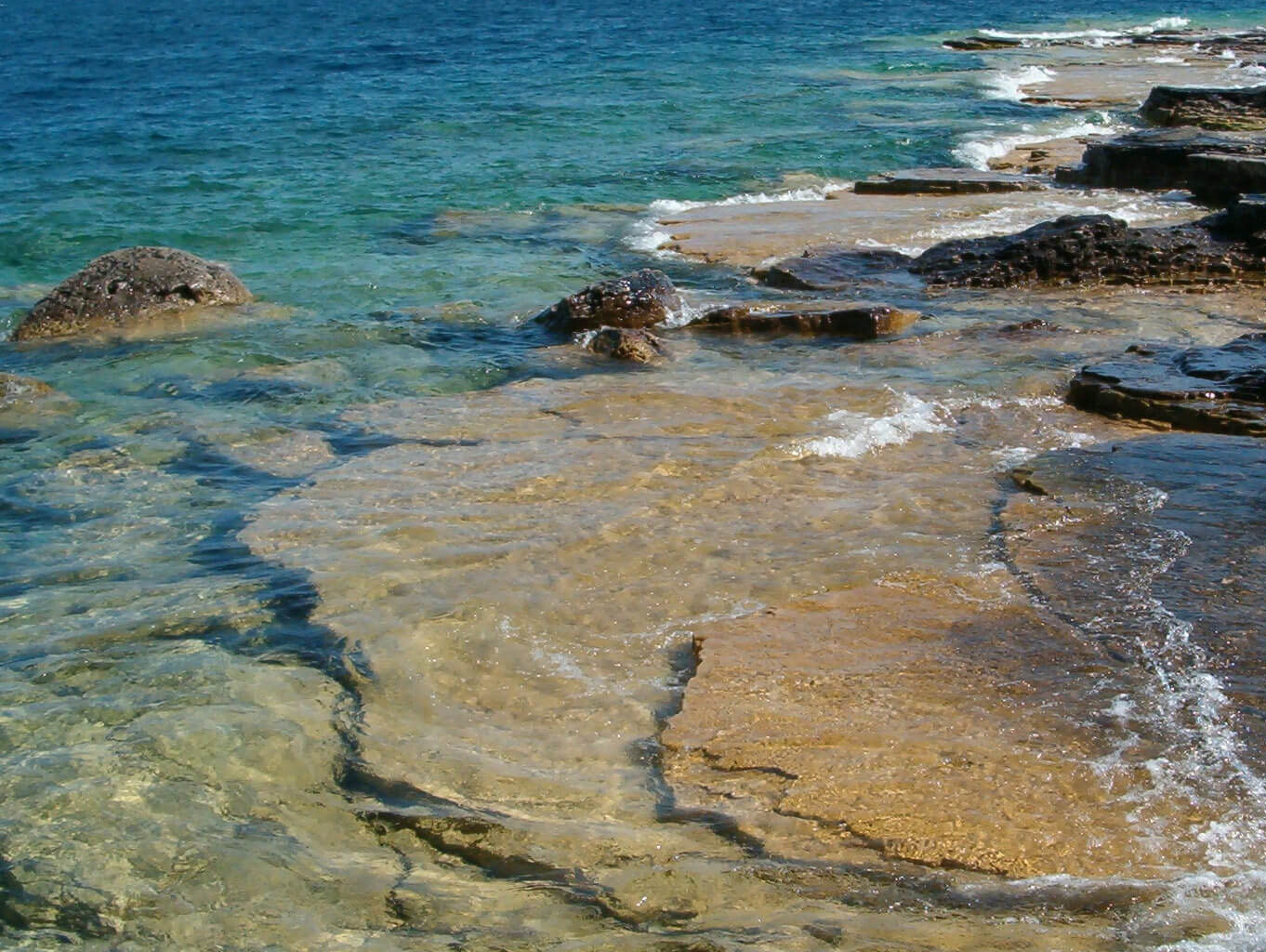
Improving and preserving water ecosystems at lakes Ontario, Simcoe and Huron
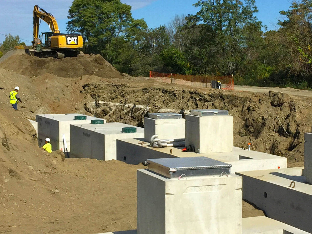
Installing a wastewater system in Amenia, NY
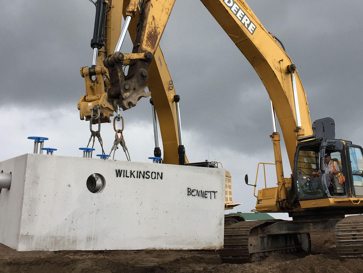
Working on an water valve chamber in Waterloo, Ontario