Installation Guidelines
Site
The installation site must be accessible to large heavy crane equipment. A firm, flat and level area of sufficient size to allow manoeuvring room for this type of equipment must be provided. This area must be free of overhead wires, tree limbs, or other above-grade obstructions which could affect normal crane operation.
Excavation
Excavation length and width should allow for a minimum of 300 mm clearance on all sides of the precast. More space must be allowed if any work is to be done on the outsides of the unit after installation. To minimize stress on a tank or chamber, it should be placed on a base of gravel or crushed stone, minimum 150 mm thick. Soil conditions must be firm and stable.
Soil Conditions
Most of our precast tanks, manholes and chambers are designed for installation in firm stable soil. Unless designed for such use our product warranty is void where an installation involves saturated/unstable soils. Regardless of any design enhancements the precast structure must always be placed on a flat, firm supporting surface.
Please consult the factory before specifying precast elements for use in unfavourable soil conditions.
Joint Seal
The mating surfaces of the joint must be clean and dry. The
lower precast section should be placed in its final position in the
excavation. The joint of this section should be made clean and dry,
then mastic strips of sealant applied. Ensure that the ends of each strip overlap by a minimum of 25mm as the sealant
is laid around the joint.
-
 The mating surfaces of the joint must be clean and
dry. The lower precast section should be placed in its final position
in the excavation. The joint of this section should be made clean and
dry, then mastic strips of sealant applied.
The mating surfaces of the joint must be clean and
dry. The lower precast section should be placed in its final position
in the excavation. The joint of this section should be made clean and
dry, then mastic strips of sealant applied. - Using lifting equipment that is safely adequate for the job, hoist each subsequent precast section a few feet above the ground in an open area away from the excavation. The joint surface of this section must now be inspected. A broom should be used to sweep away adherent debris. Care must be taken that the people preforming this task have ample room to manoeuvre and do not at any time work directly under the hanging load. Should it prove impossible to clean the joint properly in this way, the section must be safely blocked up in position allowing access from underneath.
- Once the joint surfaces are clean, dry and free of debris and extra mastic has been applied in areas where the male or female joint might have been chipped or broken in handling, the upper section can be carefully set directly onto the lower section.
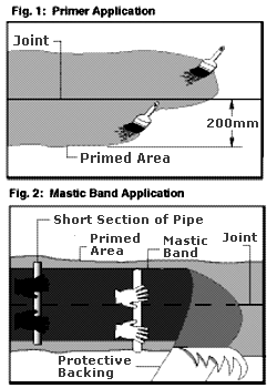
- Allow the structure to stand until the mastic is completely crushed into all parts of the joint and it stops extruding from the sides. Remove the excess mastic and ensure the outer wall is clean and dry in the area 8'' above and below the joint. Apply TWO COATS of mastic primer using a paint brush or roller to the outer wall surface (8'' above and below the joint). (See Fig.1)
- Apply the mastic membrane to the primed area making sure it is centred over the joint. The protective paper backing should be removed progressively as the mastic band is applied. Using a roller or other blunt shape, push the mastic firmly onto the primed surface rolling out any ripples or folds.(See Fig.2)
- An overlap is necessary when joints occur in the mastic band. Apply primer to back of the section that will be overlapped approximately 12''. Place the overlapping end onto the primed section and roll into place.
TESTING
Fill the precast tank or chamber with water to 18 inches (460 mm) above the connection. Observe the connection at the outside of the tank for a suitable period of time; usually between 2 - 24 hours.
Fill the tank or chamber with water to 18 inches (460 mm) above the joint. Observe the outside wall at the joint for a suitable period of time; usually 2 - 24 hours.
Fill the tank or chamber to the underside of the roof slab or to a point up inside the access riser. The access riser should be a one piece casting integral with or mechanically connected and sealed to the top of the structure. Note the liquid level, let stand for a suitable period of time and check the level.
CAUTION!
A precast vessel is subjected to internal pressure when it is filled with water. Some tall flat sided tanks or chambers rely on support from the surrounding earth to resist stress imposed by the contained liquid. It is recommended that the tank or chamber at no time be filled higher than 24 inches (600 mm) above the lowest outside level of back fill.
BACK FILLING
Back fill material must be free of boulders and large stones. Back fill must be placed in layers progressively against the four sides of the precast structure. When back filling with an excavator do not drop back fill onto the precast or into the excavation from a height greater than one metre. The wheels or tracks of back filling equipment must be kept at least one metre away from the tank or chamber. At no time should heavy equip- ment come in contact with any part of the precast.
COMPACTION OF BACK FILL
Compaction of fill around a precast tank can impose stresses sufficient to cause failure of the walls. Discretion must be used in this operation. Naturally tanks with comparatively thin walls are more susceptible to damage than some of the heavier designs.
BOUYANCY
Although concrete tanks are very heavy, they will float in a fairly shallow depth of water. If the tank or chamber must remain free of back fill for testing purposes etc., for any appreciable length of time, measures must be taken to ensure that water does not accumulate in the excavation.
Download printer-friendly PDF version [133k]
|
|
To open the pdf documents, you may need to download the latest version of Adobe Acrobat Reader. |